
Com Port – Lists available or active ports. It is up to the user to select the correct port for the mount. If you don’t know the mount port open or search for Device Manager and look in the ‘Ports (COM & LPT)’ section of the Device Manager.
Baud Rate – Rates from 300 to 230400 are available. Most mounts work at the default 9600 rate or USB at 19200.
Rates – Sidereal, Solar, Lunar, and King are present from the ascom standards. Clicking the 3 dots will confirm a reset to the default setting.
Alignment Mode – GermalPolar is the default. Others will work with the Mount set to simulator.
Equatorial System – Local or TopoCentric is the default but. TopoCentric is also known as JNOW. Other is set to apparent. The server will accept input and output to the display the coordinates selected.
Mount – The simulator will work in all alignment modes. Which mount is selected will be used when an application attempts to connect to the server.
Max Slew Rate – speeds for the hand controller are a percent of the max rate. If you want slower movements change this to a smaller number.
Minimum Dec Pulse & Minimum Ra Pulse – Warning, it’s recommended you leave this set to 20 and only change after discussing issues and options on the support forum. This option is to refine guiding to a very small step increment. A correct setting is based on baud rate, guide rate, type of mount and settings in your guiding software. 20 milliseconds is the default and will work in almost all cases. A lower setting could cause poor performance depending on the capabilities of individual mounts.
Guide Rates – A percentage of the selected rates to use for guiding. The default 50% is a good starting point for guiding with applications like PHD2.
Over Meridian Limit – degrees before or passed the meridian the mount can travel before running into a limit alert. Warning – limits will not stop the mount from moving and simply displays a warning light. It is up to the user to see that the mount is not damaged or is flipped when necessary.
Refraction – Adds the effects of light as it passes through the atmosphere to the coordinates.
Encoders – Turns on and off the internal mount encoders.
Alternating PPEC – This allows pulses from guiding software to not be truncated or cut when the mount implements PPEC. When the internal PPEC runs it’s been shown that some pulses may be randomly cut short because of the timing in PPEC changes. This problem doesn’t seem to exist for mounts using the ST4 or handbox interfaces only using an EQDir cable and the internal PPEC. The ST4 and Handbox interfaces implement a PPEC on/off strategy when dealing with pulses. This means that PPEC is turn off then the pulse is executed, then PPEC is turned back on. This strategy keep PPEC from interfering with the pulses. Using this option emulates that on/off strategy. Any mount using the internal PPEC and an EQDir cable should consider turning this option on and evaluate its long term affects. If not using the internal PPEC then there is there is no need to use this option.
Full Current – When you turn on the mount, by default the mount will track at half the watts/amperage. The full current option tells the mount not to track at half current and to use the full current. Full current is recommended unless you’re running off a battery and power consumption needs to be at a minimum.
GoTo Dec Pulse – A new alternative method when tracking and guiding. This turns pulses from guiding commands into a Dec goto command. It will slew like a normal goto which is different than the default pulse, which is based on the guide rate. GoTo slews are quicker and accurate. You can turn this on at any time even when guiding or tracking. If this option is turned off then guiding in Dec follow the normal guide rate and percentage. It’s recommended to use this option and evaluate it over the long term.
Sync Limits – When checked it enforces the mount cannot sync to targets that are greater than 30 degrees from the current position. It’s recommended to leave this checked as a safety precaution. Warning – When not checked the mount could sync to an object that is too far from its current pointing position throwing off the real axis positions to a point where the axis may end up colliding with the pier or something unintended.
Global Stop (esc) – Allows the escape key to stop the mount at any time. When check it works when the GSS window is minimized or is behind other windows. Be aware that global keys may also be hooked into to other programs that you may be running. Be sure to check if hitting the escape key will also affect them.
Park Positions – Click the + and – buttons to Add or remove park positions. Use the Set button to assign the current mount axes positions to the selected park position. You cannot edit or modify the name of an existing position but you can reset its positions using the Set button. If you need to change a name it’s best to create a new park position and then remove the old one.
Observatory Location – Latitude and Longitude of your observatory is used to calculate local positions.
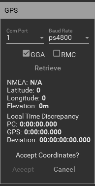
GPS – Reads a COM port for available NEMA sentences. Select GGA or RMC. GGA is the default and RMC does not contain elevation data. GS will retrieve the first found tag GNGGA, GPGGA, GNRMC, GPRMC. Hit retrieve again for another tag search. The time is also pulled for and compared against the local pc clock. Any discrepancies are displayed. If you ran GS as Administrator you will see a checkbox to update the system time. Check your Windows system options for items that may change the time again like Internet Time Services. For viewing, guiding, and imaging a few seconds off isn’t going to matter.
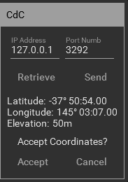
CdC (Cartes du Ciel) – With CdC server running you can connect to CdC and retrieve or send the observatory location information.
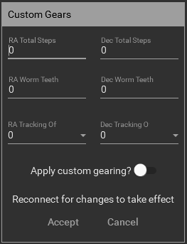
Custom Gearing – If you have replace any gears on your mount or changed the ratio then this will allow you to enter that information. Enter the total steps for Ra and Dec along with the total teeth count for each worm gear. The total steps divided by the total worm steps will give you the total worm teeth count. Only integers are allow so only round down if the total worm steps are a fraction. Leave the tracking offset at zero until a drift test is done to determine if any offset is needed. The offsets numbers relate to a small percentage of Sidereal to apply along with the tracking rates when tracking. Also, the offset will only be applied if tracking is below 2x normal sidereal speed.
To use the custom gearing be sure to turn on the “Apply custom gearing” toggle button. Use the Connect/Disconnect button as all changes require a new connection to the mount. When the custom gearing is being applied the gear icon color will change to the selected accent color.
WARNING: Only enter the custom information if different gearing was put in the mount. Using the default gearing from SkyWatcher does not require the custom information. Entering invalid information can result unexpected results and possible harm to the mount. If you do not know what gearing is in the mount please use one of the support links at the end of this manual.
External Capabilities – Settings that tell external applications the capabilities of the driver.
Can Set Park – When checked this allows external applications to set the telescope Park position to the current telescope position. The default is checked.