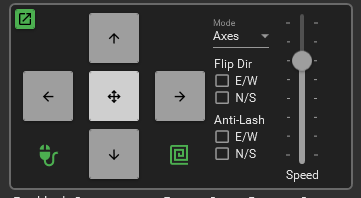
Speed – 8 settings to control the speed of the hand controller buttons. All speeds are relative to the Max Slew Rate in settings.
Mode – The direction of the hand controls are base on which mode is selected; Axes, Guiding, and Compass.
Guiding – Follow guiding directions in the same way guiding programs calibrate NESW with pulses for guiding. The following is defined by the ASCOM standard and would always apply. The user could not flip directions.
North (+ declination/altitude)
South (- declination/altitude)
East (+ right ascension/azimuth)
West (- right ascension/azimuth)
Axes – Follow clockwise and counterclockwise directions of the axis. User would be able to set a flip switch for N vs S Hemi directions. Axis1 would be Ra/Az and Axis2 would be Dec/Alt
North (CW Axis2)
South (CCW Axis2)
East (CW Axis1)
West (CCW Axis1)
Anti-Lash – attempts to compensate for mechanical backlash errors in the mount when using the hand controls. Use the checkboxes to turn off/on the compensation for each axis. Best used at slower speeds when trying to use the hand controls to keep an object aligned.
E/W – Works when tracking is on and is based on the amount in the Backlash RA setting. If there is backlash in the RA axis each move east will move the lash to the wrong side. This will move the mount proportionally back to the west trying to remove the backlash so tracking will re-engage without having to travel the backlash distance.
N/S – Works when reversing the N/S direction and is based on the amount in the Backlash Dec setting. When the reverse direction is applied the compensation is applied before the actual move. This takes up the backlash in Dec before the reverse move is applied. Each reverse direction the backlash will be proportionally applied.
– Opens a separate or new window for the hand controller. You could open this then minimize the GSS application so you have more screen room for other applications.
– Mouse lock. When you engage the lock you can then pick up the mouse and move to the mount where you can control certain movements. Left click this button and the mouse will lock and not allow movement of the cursor. A popup message will appear as a reminder it’s on. At the same time it enables the mouse buttons for the mount controls below. It’s recommended to have a 3 to 5 button mouse with a wheel.
- Press any keyboard key to stop or return the mouse cursor.
- Left or Right click for Dec or RA movements
- Center wheel to increase or decrease speed.
- Center wheel click to switch between RA or Dec control
- X1 button for Spiral Search “Out” command
- X2 button for Spiral Search “In” command.
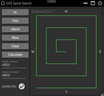
The spiral contains dark points or dots that represent each goto coordinates. If no points exist then the next button movement ‘Out’ or clicking ‘New’ will create them. Right click on any point and a goto dialog will appear.

In – Executes a goto to the next inward point. Once at the center the button will do nothing. Available as a gamepad command.
Out – Executes a goto to the next outward point. Once at the end the button will do nothing. If no points exist they will be created on the first outward move. Available as a gamepad command.
Abort – Stops any goto movement but keeps tracking on. Available as a gamepad command.
New – Creates a new set of points or goto coordinates for the spiral. Available as a gamepad command.
Clear – Removes the points from the spiral
Calculate – Opens the dialog to calculate the needed width and height settings
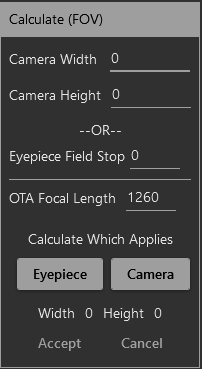
All settings are entered in millimeters (mm). If searching with a camera enter the camera width and height along with the OTA focal length then click the Camera button. When using an eyepiece enter the field stop and OTA focal length and click the Eyepiece button. When the width and height are populated select accept to copy these values to the spiral window.
The search strategy is to create an invisible search box using the Width and Height as the field of view (FOV) size. Each point created on the spiral represents is a single FOV.
Width – The FOV width in seconds of arc
Height – The FOV height in seconds of arc
Use the Calculate button to assist in setting theses.
Limits On – When ‘On’ or check marked two limits will be imposed; 1) Meridian flips will not occur, so an ‘Out’ movement would do nothing if it required a flip. 2) Distance is a defined as the area around the spiral. Anytime the mount moves beyond that area the spiral will reset and no points will be defined. The distance is displayed at the top of the spiral and is the angular distance from the center of the spiral to its farthest point plus another 40%. Anywhere within this area you are free to move the mount how you want and the spiral will not reset.
Tips – As you move closer to the poles and away from the celestial equator the RA or Width movements will overlap exponentially. If you want Dec to overlap set the seconds of arc to a slightly smaller number.
How to calculate FOV in arc seconds
http://astronomy.tools/calculators/field_of_view/
The Field of View Calculator at Astronomy tools is probably one of the better online tools. For imaging mode simply enter the equipment information and calculate the Field of View. Take the smaller of the 2 numbers in degrees and multiply it by 3600. i.e. 2.01° x 1.37°1.37 degrees x 3600 = 4932 arc seconds. Enter 4932 into the Spiral Search Arc Seconds.
An alternative to the online tool for a sensor is it to do the calculation manually. To do this, use the smaller side of the chip. (Width of chip in mm * 3460) / (focal length of optic train in mm) = arc minutes * 60 = arc seconds. i.e. 13mm * 3460 / 545mm = 82.5 arc minutes = 4951 arc seconds
another alternative for sensors is to take the smaller pixel size divide by focal length then multiply by 206.3 to get arc seconds per pixel. Multiply that by the amount of pixels on the smaller side of the chip. At binning 1 use the following formula. i.e. 4.63um / 545mm * 206.3 = 1.75 arc seconds per pixel * 2822mm = 4945.8 arc seconds
For eyepieces use visual mode on the field of view calculator. Enter the equipment, take the field of view and multiple by 3600. 1.1°* 3600 = 3960 arc seconds. The manual formula is Scope Focal Length / Eyepiece Focal Length = Magnification. Eyepiece FOV in degrees / Magnification = real Field of view in degrees. Multiply that by 3600 for the arc seconds. i.e. 545mm / 10mm = 54.5 mag. 60deg / 54.5mag = 1.10091 * 3600 = 3963 arc seconds